
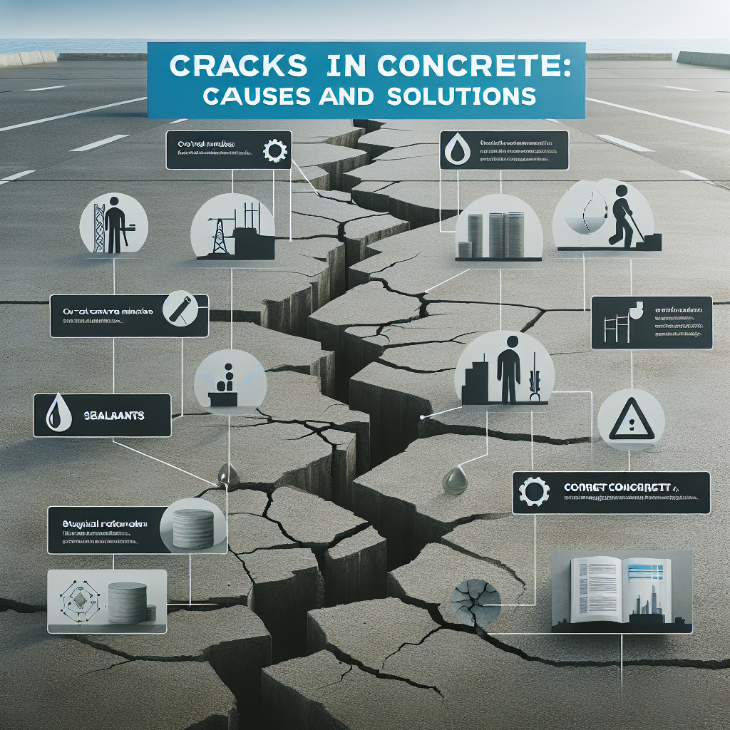
Introduction Concrete cracking remains a common challenge in construction that can lead to structural vulnerabilities, maintenance costs, and safety risks. Although concrete performs very well under compression, its tensile strength is low, approximately 10-15 percent of compressive strength, making it susceptible to cracking when stresses exceed its capacity. Executing high-quality concrete work through proper material selection, placement techniques, and curing protocols is essential to mitigate these vulnerabilities.
Section: Failure Analysis — Why Concrete Cracks Cracks appear when stresses exceed the material's tensile capacity. The main mechanisms and signs for diagnosis are described below.
1. Plastic Shrinkage Cracking Mechanism: rapid moisture loss generates capillary stresses greater than the concrete's early tensile strength. A practical expression for the evaporation rate is Evaporation Rate kg/m2/h = 0.313 × (wind speed m/s + 0.318) × (saturated vapor pressure at concrete temperature - ambient vapor pressure). Triggering conditions: wind above 5 mph, relative humidity below 50 percent, concrete temperature above 90 F, mixes with low bleeding such as those containing silica fume. Identification: shallow, irregular cracks appearing between 0 and 12 hours after placement.
2. Drying Shrinkage Mechanism: moisture loss causes volumetric reduction. A typical strain development curve can be approximated by epsilon = epsilon_sh × t / (a + t) where epsilon_sh is the ultimate shrinkage, on the order of 500 to 800 microstrain, t is time in days, and a is a constant approximately 35. Key factors: high water/cement ratio, high-shrinkage aggregate type, and thin or slender sections that crack more easily. ACI 209R guide provides reference values; for example, concrete cured under humid conditions may exhibit shrinkage around 780 × 10-6.
3. Thermal Contraction Mechanism: temperature drops induce contraction according to delta L = alpha × L0 × delta T, where alpha is the coefficient of thermal expansion typically between 5.5 and 10 × 10-6 per degree F. Critical scenarios: daily temperature fluctuations greater than 20 F, mass concrete with internal heat such as dams, and restraint at corners or fixed ends. ACI 207.2R recommends that the maximum temperature difference between core and surface be kept below 35 F to avoid thermal cracking.
4. Settlement Cracks Mechanism: differential ground movements generate flexural stresses. As a reference, the approximate soil pressure q is expressed as q = gamma × Df, where gamma is the unit weight of soil and Df the fill depth. Common causes: insufficient bearing capacity, poor compaction below 90 percent of Proctor density, and erosion due to hydraulic gradients. Practical geotechnical rule: settlements greater than 25 mm usually indicate significant problems.
5. Reinforcement Corrosion Cracking Electrochemical process: oxidation of reinforcement generates corrosion products whose volume is between 3 and 6 times the original steel volume, creating tangential stresses that fracture the concrete. Simplified reactions: anode Fe becomes Fe2 plus electrons; cathode consumes oxygen and water to form hydroxyls. Accelerating factors: chloride content above 0.4 percent by weight of cement, carbonation exceeding the concrete cover. NACE SP0290 standard indicates that corrosion rates above 1 mil per year require intervention.
Section: Repair Methods — Evidence-Based Protocols The selection of repair depends on crack width, activity, and structural significance.
Capillary cracks smaller than 0.3 mm Recommended technique: surface sealing. Procedure: clean with compressed air and compatible solvent, apply low-viscosity polyurethane sealant and cure at temperatures above 10 C for 24 hours. Effectiveness: reduces water ingress by up to 95 percent but does not provide structural capacity.
Medium cracks between 0.3 and 5 mm Recommended technique: epoxy injection. Procedure: prepare by drilling ports every 150 mm, flush and roughen the surface, inject epoxy at controlled pressures until overflow. Test adhesion using pull-off testing per ASTM D4541; ACI 224.1R suggests reference strengths above 200 psi to restore structural continuity.
Structural cracks greater than 5 mm or active Techniques: stitching using U-bars installed transversely, carbon fiber reinforcement, or rehabilitation through shoring and micropiles. Sizing rule for stitching: approximate bar diameter equal to 10 times the crack opening in mm as a starting point, and for FRP reinforcements apply ACI 440.2R criteria where P_fr = 0.9 × A_fr × f_fu. For settled foundations, it is recommended to install helical piles until reaching installation torques indicating capacity, for example greater than 4500 ft-lbs per design.
Corrosion Repairs Procedure: expose up to 25 mm behind the reinforcement per ICRI 310.1, clean the steel by abrasive blasting to Sa 2.5 grade ISO 8501-1, apply migrating corrosion inhibitor and rebuild with shrinkage-compensating mortar complying with ASTM C1107. Quality control: non-destructive ultrasonic testing ASTM C597 and load tests up to 150 percent of service load for critical cases.
Section: Prevention — Engineering Controls Effective prevention is based on design, materials, and good construction practices.
Mix Optimization Water control: keep the water/cement ratio below limits according to exposure; for example, non-aggressive exposures may allow ratios close to 0.50, moderate exposures 0.45, and severe 0.40. Use of admixtures: shrinkage reducers can decrease shrinkage between 30 and 50 percent; air entrainment between 5 and 8 percent to resist freeze-thaw cycles per ASTM C231.
Joint Design Control joints: typical spacing 24 to 30 times the slab thickness per ACI 302.1R and cut depth of 0.25 of the thickness. Isolation joints: around columns, drains, or walls use compressible materials such as 12 mm asphalt-impregnated board.
Curing Protocols Duration: for Type I cements minimum 7 days of moist curing, for Type III at least 3 days as a reference. Methods: moist curing maintaining relative humidity above 95 percent or application of curing compounds at typical coverage rates of 200 ft2 per gallon per ASTM C309.
Reinforcement Strategies Cover requirements: follow ACI 318 with minimum covers according to exposure, for example slabs on grade 50 mm, walls 38 mm, and marine exposures 75 mm. Use of fibers: steel fibers between 0.5 and 1.5 percent by volume for crack control and synthetic fibers 0.1 percent to control plastic shrinkage.
Subgrade Preparation Compaction: achieve at least 95 percent of Proctor density ASTM D698 and verify with nuclear equipment if applicable. Drainage: ensure adequate permeabilities, slopes of 1 to 2 percent directing water away from structures.
Quality Control and Testing Implement material acceptance testing, temperature and humidity control on site, crack monitoring with crack gauges, and resistivity sampling to assess corrosion risk. Early instrumentation and periodic reviews facilitate early and economical actions.
Conclusions and Key Recommendations Diagnose first: map crack patterns to identify dominant mechanisms. Repair strategically: match the technique to crack severity, from sealants for microcracks to FRP reinforcements or shoring for structural damage. Prevent proactively: optimize mix design, joint spacing, and curing. With rigorous analysis and precision engineering, it is possible to ensure concrete durability for decades.
About Q2BSTUDIO Q2BSTUDIO is a custom software and application development company specialized in advanced technological solutions for the construction and engineering sector. We offer custom software, custom applications, artificial intelligence and AI services for businesses, AI agents for task automation, cybersecurity consulting, AWS and Azure cloud services, and business intelligence services with Power BI to transform data into decisions. We can develop custom applications to monitor cracks, integrate predictive shrinkage and corrosion models based on artificial intelligence, deploy cloud solutions, and secure the platform against threats with first-class cybersecurity practices.
Call to Action If you need to evaluate concrete pathology, design repair strategies adopting ACI and ASTM standards, or digitize quality control through custom software solutions, contact Q2BSTUDIO for technical consulting and a comprehensive solution proposal that includes application development, artificial intelligence models, cloud integration on AWS or Azure, and dashboards with Power BI.
Keywords custom applications, custom software, artificial intelligence, cybersecurity, AWS and Azure cloud services, business intelligence services, AI for businesses, AI agents, power bi